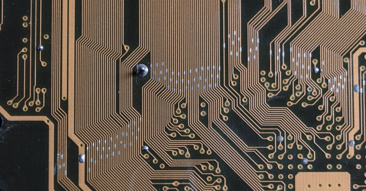
Teardrops refer to the practice of smoothly blending the copper trace into the pad or via, creating a teardrop or fillet-like shape. While not universally applied, teardrops offer a range of potential benefits, but also introduce certain drawbacks that designers must carefully consider.
This article explores the pros and cons of utilizing teardrops, helping designers make informed decisions about their implementation.
The Advantages of Teardrops:
Teardrops primarily address reliability and manufacturability concerns, offering several key advantages:
- Improved Mechanical Strength: One of the most significant benefits of teardrops is their ability to enhance the mechanical strength of the connection between the trace and the pad/via. Traditional right-angle connections can be stress concentration points, making them susceptible to cracking or fracturing, especially during assembly, rework, or thermal cycling. The smooth transition created by a teardrop distributes stress more evenly, reducing the risk of failure. This is particularly important for boards subject to vibration, flexing, or harsh environmental conditions.
- Enhanced Signal Integrity: Teardrops can positively impact signal integrity, especially at higher frequencies. The gradual transition minimizes impedance discontinuities that can cause signal reflections and distortions. While the improvement might be subtle in many cases, it can be crucial for high-speed digital and RF designs. The smoother shape helps maintain a more consistent characteristic impedance along the trace.
- Increased Manufacturing Yield: Teardrops can improve manufacturing yields by reducing the likelihood of acid traps during the etching process. Sharp corners in traces can trap etching chemicals, leading to over-etching and potential trace damage. The rounded shape of a teardrop minimizes this risk, resulting in cleaner and more consistent trace definition. This is particularly relevant for boards with fine lines and spaces.
- Improved Solderability: For through-hole components, teardrops can improve solder flow and wetting during the soldering process. The teardrop shape provides a larger surface area for solder to adhere to, promoting a stronger and more reliable solder joint. This is especially beneficial for hand soldering or wave soldering processes.
- Enhanced Thermal Performance: In some applications, teardrops can contribute to improved thermal performance. The increased copper area near the pad/via can help dissipate heat more effectively, particularly for high-power components. This can help reduce thermal stress and improve the overall reliability of the board.
The Disadvantages of Teardrops:
Despite their advantages, teardrops also present some potential drawbacks that designers need to be aware of:
- Increased Design Complexity: Implementing teardrops adds an extra layer of complexity to the design process. Designers need to carefully consider the size and shape of the teardrops, ensuring they comply with design rules and don’t create other issues. This can increase design time and effort.
- Potential for Increased Board Space: Teardrops can consume additional board space, especially if they are large or if the board is densely populated. In space-constrained designs, this can be a significant concern. Designers need to balance the benefits of teardrops against the potential impact on board size.
- Manufacturing Challenges: While teardrops can improve manufacturing yields in some cases, they can also introduce new challenges. The added copper can make the etching process more complex, and it’s essential to ensure that the teardrops are properly defined to avoid any manufacturing defects.
- Increased Cost: The added design complexity and potential manufacturing challenges associated with teardrops can translate to increased costs. This is especially true for complex boards with a large number of teardrops.
- Signal Integrity Concerns (at very high frequencies): While generally beneficial, in extremely high-frequency applications, poorly designed teardrops can sometimes introduce parasitic capacitance or inductance, negatively impacting signal integrity.
Design Considerations for Teardrops:
If a designer decides to use teardrops, several factors should be considered:
- Teardrop Size and Shape: The size and shape of the teardrops should be carefully chosen based on the specific application and design requirements. Too large a teardrop can consume excessive board space, while too small a teardrop might not provide sufficient benefits. The shape should be smooth and gradual to avoid any sharp corners.
- Design Rules: Specific design rules should be established for teardrops, defining their size, shape, and placement. These rules should be enforced during the design process to ensure consistency and avoid any issues.
- Placement: Teardrops should be placed strategically, focusing on critical connections that are subject to stress or high-frequency signals. It might not be necessary to apply teardrops to every connection on the board.
- Manufacturing Capabilities: The manufacturing capabilities of the chosen PCB fabricator should be taken into account when designing teardrops. The fabricator should be able to reliably produce the desired teardrop shapes and sizes.
When to Use Teardrops:
Teardrops are particularly beneficial in the following situations:
- High-stress applications: Boards subject to vibration, flexing, or thermal cycling.
- High-speed digital and RF designs: Where signal integrity is critical.
- Boards with fine lines and spaces: Where etching issues are a concern.
- Through-hole components: To improve solderability and mechanical strength.
- High-power applications: To enhance thermal performance.
When to Avoid Teardrops:
Teardrops might not be necessary or desirable in the following situations:
- Space-constrained designs: Where board space is at a premium.
- Simple, low-frequency designs: Where signal integrity and mechanical stress are not major concerns.
- Cost-sensitive applications: Where the added cost of teardrops is not justified.
Conclusion:
Teardrops offer a valuable tool for PCB designers, providing sone benefits in terms of reliability, manufacturability, and signal integrity. However, they also introduce design complexity and potential cost increases. By carefully considering the pros and cons, and by following appropriate design guidelines, designers can make informed decisions about where to use teardrops and where not, striking a balance between performance, reliability, and cost. Modern PCB design software often includes automated teardrop generation features, which can simplify the implementation process while still allowing designers to customize their size and shape. Ultimately, the decision to use teardrops should be based on a thorough understanding of the specific requirements of the design and the trade-offs involved.


